You may have seen this article where I discussed a 640x480 VGA signal generator that I designed and built. The signals, that circuit generated, were correct when measured with an oscilloscope. However, I concluded that I didn’t know why my display hardware had a hard time displaying an image and I found the reason for that and updated the circuit to generate the necessary signals for displaying an 800x600 image with a refresh rate of 60 Hertz.
Let me introduce you to the updated revision. While I do that, I’ll also outline the differences to the last version and the faults of it.
How VGA signals work
Take a look at the previous article if you’re interested in a detailed explanation.
Timings
As discussed in the previous article, the monitor needs an HSYNC and a VSYNC signal to determine, when a line starts and when a frame ends. These signals must be as accurate as possible. The HSYNC timings for an 800x600 image with a refresh rate of 60 Hz are as follows:
| Scanline part | Pixels | Time [µs] |
| Front-Porch | 40 | 1 |
| Sync-Pulse | 128 | 3.2 |
| Back-Porch | 88 | 2.2 |
| Active-Video | 800 | 20 |
Which sums up to a total of 1056 Pixels per line and each line takes around 26.4 microseconds to be drawn. Each frame consists of 600 visible lines and is then followed by a VSYNC-pulse with the following timings:
| Frame part | Lines | Time [ms] |
| Front-Porch | 1 | 0.0264 |
| Sync-Pulse | 4 | 0.1056 |
| Back-Porch | 23 | 0.6072 |
| Active-Video | 600 | 15.84 |
Unlike the 640x480 image, both sync-pulses (HSYNC and VSYNC) are positive.
The updated circuit
The old version used a 25.0 MHz quartz oscillator. This one, however, runs on a 10.0 MHz oscillator. I decided to use that one because it was easier to troubleshoot. However, a 20.0 MHz (or any multiple of 40.0 MHz) one should work just as fine. But make sure to update the circuit if you change the oscillator.
Anyway, just like the last version, the circuit works by counting the rising edges of the clock signal (the 10 Mhz oscillator). When it reaches a certain count, it outputs a well-defined state on the VGA synchronization lines to tell the monitor, it’s attached to, to start a new line or frame.
When the circuit starts, the HSYNC line is in a high state and, therefore, tells the monitor to start a new line. It remains in that state for exactly 32 clock cycles (10 MHz). Then, the HSYNC line gets pulled HIGH for the rest of the line (see the table above and the previous article for details) before getting pulled low again. When a line ends, the line counters are reset.
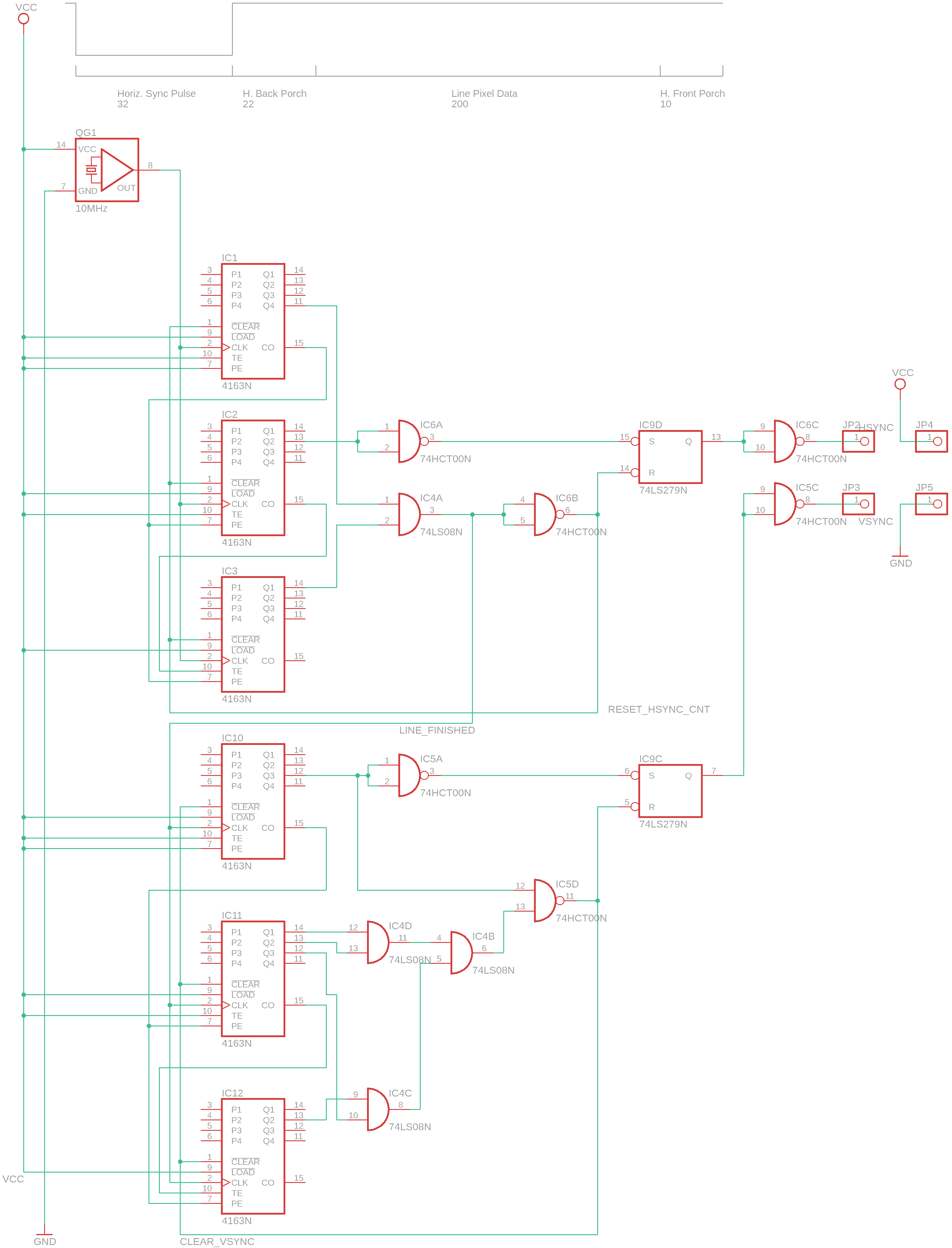
Figure 1: The counting circuit (Click here for full resolution)
Furthermore, whenever a line ends (the HSYNC line gets pulled from HIGH to LOW), the VSYNC counter gets incremented by one. When the circuit starts, the VSYNC output is also in a high state. However, after being incremented once, the VSYNC line gets pulled into a high state and remains there for the rest of the frame. When the last line gets drawn, the VSYNC counter is reset and a sync pulse is initiated again.
This cycle repeats as long as the circuit is enabled.
Wiring the VGA connector
Unlike stated in the previous article, it’s necessary to connect all the pins of the VGA connector. Otherwise, some monitors might not function properly or will refuse to detect a signal.
I connected the pins of a D-SUB 15 connector according to the following table and image:
| Pin # | Description |
| 1 | Red |
| 2 | Green |
| 3 | Blue |
| 5 | GND (HSYNC) |
| 6 | GND (RED) |
| 7 | GND (GREEN) |
| 8 | GND (BLUE) |
| 9 | +5V |
| 10 | GND (VSYNC) |
| 13 | HSYNC |
| 14 | VSYNC |
The following image shows the female side of the connection (The one that’s on the graphics card):
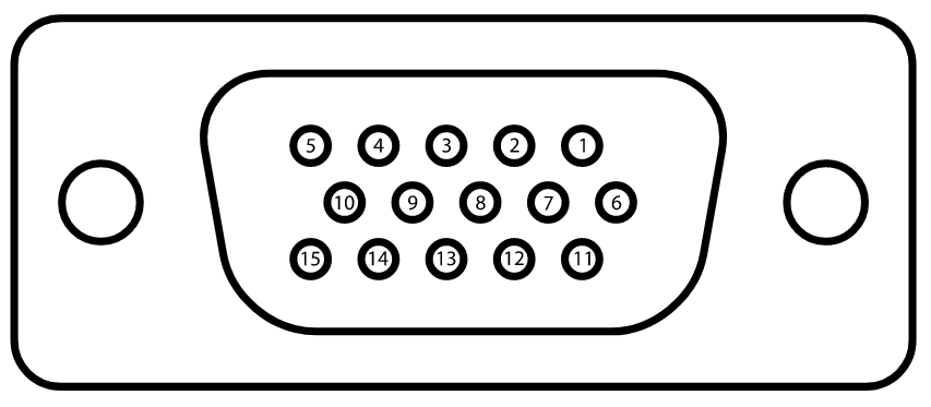
Figure 2: Pins of the VGA connector
Parts used
| Quantity | Name | Description |
| 6 | 74LS163AN | 4-Bit binary counter with fast look-ahead |
| 1 | 74LS08N | Quadruple AND-Gate |
| 2 | 74HCT00N | Quadruple NAND-Gate |
| 1 | 74LS279N | Quadruple R/S Flip-Flop |
| 1 | - | 10MHz quartz-oscillator |
| 1 | - | DSUB-15 (VGA-Connector) |
Generating the RGB information
As discussed before, the RGB signals are analog signals with a value between 0.0V and 0.7V for each of the colors. This circuit can only generate the synchronization signals and you’ll, therefore, have to use an external device to generate the image itself.
I used an Arduino Nano to fill the entire screen with a solid color after each VSYNC signal. You can download the code here. You’ll need to connect the three analog color lines to A0, A1, and A2 and the VSYNC signal to Pin 2 of the Arduino. It will then ask you to input a color and, if done correctly, it’ll display it on a screen.
Conclusion
The old design had a few flaws. One of them was the quartz-oscillator I used. It was a bit too slow (25.0MHz instead of 25.175MHz) and I think that caused the display to get out of sync every once in a while.
However, my biggest mistake was not connecting all the lines on the VGA connector. Every ground pin references a different signal and has to be connected correctly for this to work. In my case, it was sufficient to use a single common ground as a reference.
Anyway, after I figured that out, it was easy to upgrade the circuit to display an 800x600 image. Currently, it can only display solid colors but I’ll continue to work on this project and keep you updated.
Two alternatives
I found two articles while doing my research that discuss two alternative approaches. One author used an FPGA and the other article talks about an implementation with an MCU:
VGA with a Basys-3 FPGA
Homemade VGA adapter with an MCU
Sources
VGA 800x600 timings
VGA connector pinout
Image sources
[Figure 2] VGA connector pinout