An update on the project
Obsolete information! Please view this article for a complete and easier guide!
It’s been a while since I posted something about the wordclock build. I want to apologise for that. I’ve been somewhat busy because of the university and I haven’t quite found the time to write about the project. Also it took me some tries to make the PCB at home. It took five tries until I was satisfied with the outcome.
After I was finished with the PCB, I decided to make a revision of the design, which is easier to etch and really only has three vias, you’ll have to do manually. So this one is way easier to craft:
[caption id=”attachment_5035” align=”alignnone” width=”2292”]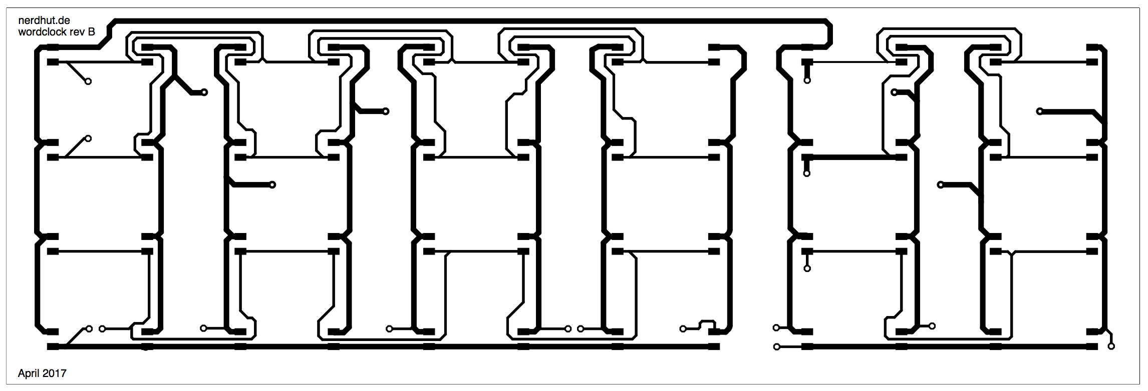 Figure 1: The wordclock PCB revision B[/caption]
The first thing you might notice is the missing LED-controller IC. I took if off the matrix PCB and placed it on a separate daughterboard. This way the matrix PCB is easier to etch and it has way less vias. It’s also easier to change it’s size. You want a larger or smaller wordclock? Now you just have to move the LEDs around and don’t have to worry a lot about the IC being in the way.
[caption id=”attachment_5051” align=”aligncenter” width=”496”]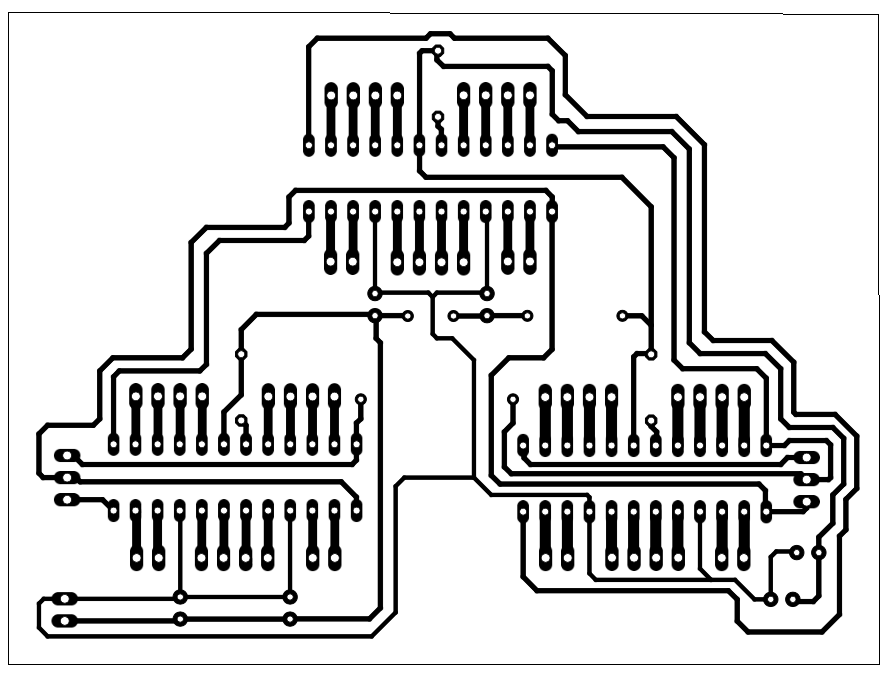 Figure 2: The daughterboard with all the controlling components of the clock[/caption]
Another big change here is that there are larger spaces between the single traces. This way it’s easier for you to craft these boards at home.
Downloads
PDF files for printing
Download the PDF files for printing here!The final version is available in the last part of this series!
Eagle project files
Download the LED-Matrix PCB here.The final version is available in the last part of this series!
Note: The daughterboards are going to be uploaded separately. I’ll also post the links here. Just needs some final touches.
Download the logic-board PCB:
Revision A
Revision B
Revision C
Revision A only contains the LED-Matrix controller ICs. It has a 3 pin-header connector for I2C and another data line and a 2 pin-header for power input, so you can use any microcontroller you want to control the matrix.
Revision Bis for the use with an Arduino nano, so no external connectors here and it has the outlines of the nano v3 directly on the board, so it can be plugged right in.
Revision C is like rev B but it has a connector for an external light sensor, which I’m going to use in my build.
All the revisions tunnel the I2C so you can daisy chain other devices (like the RTC I’m going to use) to the PCB!
Use which ever you like the most or which suits your project the best!
Next steps
Currently there are holidays, so I really want to finish this project in the next two weeks, but I don’t want to promise anything. However I’ll try my best!
Table of contents
Part 1 – First steps
Part 2 – The Electronics
Part 2.1 - Quick update and Board Rev. B (you are here)
Part 3 – The Software
Part 3.1 - Updated Revision
Part 4 – Completing the build (Not released yet)
Addendum: